


Reading an anchor bolt plan can be intimidating if you are not familiar with the details. In this article, we will decipher the anchor bolt plan you will receive from Fortify Building Solutions when you order your custom-designed steel building.
While it is likely that you will not be pouring your own concrete, a basic understanding of how to read these plans can potentially save you costly and time-consuming mistakes from mis-placed bolts. Please refer your concrete company to this page, or directly to your project consultant, if they have any questions about the plans or bolt placement.
Fortify does not supply anchor bolts. When your building is delivered, you will ideally have your foundation already poured and cured so that erection can begin immediately. Since the bolts are part of the foundation construction, it is the customer’s responsibility to purchase the proper quantity and sizes of bolts. Fortify does not recommend drilling expansion bolts into an already poured foundation; the best way to ensure maximum structural integrity of your building is to place the bolts as directed into the wet concrete and let it cure around them.
Note: An anchor bolt plan is not a foundation design. It is provided to show detailed placement of the bolts on which your columns will rest.
Drawings
In the drawings you receive, there will be three pages pertaining to anchor bolts. You should provide copies of those pages to your concrete company so they can use them as a map to place the bolts when pouring your foundation.
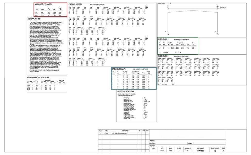
Details about each of the three color-coded sections are below. The color coding is here for demonstrative purposes, so that you can see where each section is located on the page.
How Many Bolts Do I Need?
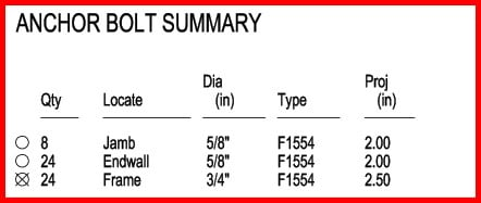
The Anchor Bolt Summary tells you the quantity of anchor bolts you will need in the various diameters required for your building. It also tells you for what part of the building the bolts will be used.
The Jamb and Endwall bolts are the same – they are just broken out by placement. In the example above you can see that you will need a total of thirty-two 5/8” diameter F1554 bolts.
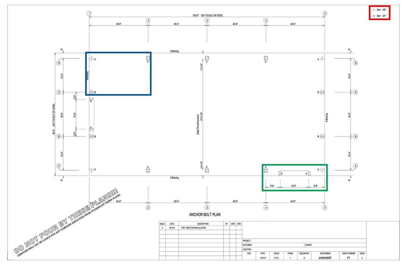
For the framed openings on this sample building, you can see that you will need twenty-four 3/4” diameter F1554 bolts. The frame bolts have an X through them, which is carried over on the diagram page to provide a visual cue as to which bolts go where.
Bolt Projection
The bolt projection is listed in the far right column. Bolt projection is important, as it accounts for the thickness of the baseplate that will be placed onto the bolt and the nut that will be used to secure the column and baseplate to the foundation. When the nuts are tightened, they should not be flush with the top of the bolt – it is recommended that at least 1-2 threads are showing above the nut. The 5/8” bolts in the sample building require a 2” projection, while the 3/4” bolts require a 2 ½” projection.
Walk Doors
Walk doors are self-framing, so they do not require framed openings to be built into the design of the building. As such, the anchor bolt quantity and locations are not included in these plans. You will, however, need to place anchor bolts for the doors when you are placing the rest. Most walk doors will need four 1/2” diameter bolts per door, with a 2” projection. Talk to your project consultant or third-party manufacturer to receive plans for your chosen walk doors.
Walk doors are field-located. This means you can place a walk door almost anywhere on a wall by simply using nibblers to cut out an opening in your paneling, then anchoring the frame to the foundation and fastening the wall panel to the frame.
Note: As mentioned above, walk doors can be placed almost anywhere. The exception is in a bay that has been designed to have cable bracing. As such, it is important to decide where your walk doors will be located during the design process, so your project consultant can make sure to place necessary cable bracing in a different bay.
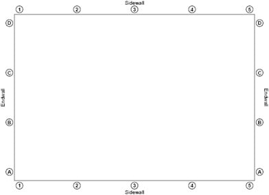
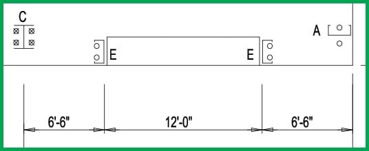
On the diagram page, your building will be shown in a grid format like the one above. The letters indicate column placement on the endwalls, and are referred to as Column Lines. The numbers indicate column placement for the sidewalls, and are referred to as Frame Lines.
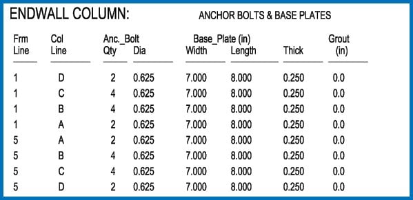
The Endwall Column section of the summary page shows a detailed breakout of which bolts will be placed at the intersections of the endwalls. In this sample building, for example, two 5/8” bolts will be located at 1D, four 5/8” bolts will be located at 5B, and so on. The baseplate and column that will be fitted onto all of these bolts will be 7 x 8 x 1/4” in size.
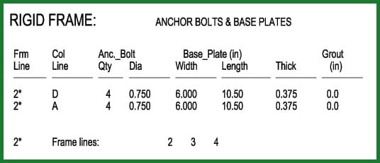
The Rigid Frame section of the summary page shows a detailed breakout of which bolts will be placed for the columns between the endwalls, at the sidewalls. There are three frame lines for this sample building; however, the quantity is only listed once for frame line 2. It will need to be multiplied by three for the other two frame lines. So you can see from the example that four 3/4” bolts will be located at 2D, 2A, 3D, 3A, 4D and 4A. A total of 24 bolts will house six 6 x 10 ½ x 3/8” baseplates.
The remainder of the information on the summary page pertains to the building’s reactions. This information is what your foundation engineer will need to properly design your piers and footing; is not pertinent to determining the number of anchor bolts needed.
Details about each of the three color-coded sections are below. The color coding is here for demonstrative purposes, so that you can see where each highlighted section is located within the page.
Details about each of the three color-coded sections are below. The color coding is here for demonstrative purposes, so that you can see where each highlighted section is located within the page.
X-Bracing
The sample building will require X-bracing, or cable bracing, on each wall. The diagram indicates where the X-bracing should be placed in the building. Make sure that you do not plan to place walk doors in these bays. If you see a conflict, notify your representative so they can revise the building design.
Walk doors are field located and self-framing, and as such are not indicated on this diagram. More information on walk doors is available in Part 1 of this series.
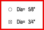
Bolt Diameters
This sample building will utilize two different kinds of anchor bolts – 5/8” and 3/4″ diameters. The legend, to the left, lets you know on the plan diagram which diameter of bolts will go where in the building. In the sample building, the columns for the inside frame lines will be bolted with 3/4″ anchor bolts, and the two endwalls and two framed openings will use the 5/8” bolts. You can see on the diagram that twenty-four 3/4″ and thirty-two 5/8” bolts are needed. The Anchor Bolt Summary page also lists how many of each size of bolts you will need.
Column Types
This sample building uses three types of configurations for the structural columns. A indicates a single C-channel with a plate attached to the bottom, anchored by one 5/8” bolt on either side of the web. Configuration A occurs on each of the four corners of the building.
B indicates two C-channels placed back to back, with a plate attached to the bottom and anchored by four 5/8” bolts – two on each side of the web. Configuration B occurs four times, on each of the interior columns of the two endwalls.
C indicates an I-beam column with a plate attached to the bottom, anchored by four 3/4″ bolts – two on each side of the web. Configuration C occurs six times, on each of the two columns that make up the three interior frame lines.
Framed Openings
This sample building has two identical framed openings for overhead doors – D and E. The columns that frame the doors are a single C-channel with a plate attached to the bottom. You will notice, however, that the bolt configuration for this column is different from Configuration A, which also use single Cs.
Bolt Configurations
The diagram shows 5 different bolt configurations for the anchor bolts, labeled as A, B, C, D, and E. A, B, and C are the structural columns. D and E are the overhead door framed openings, and are the same.
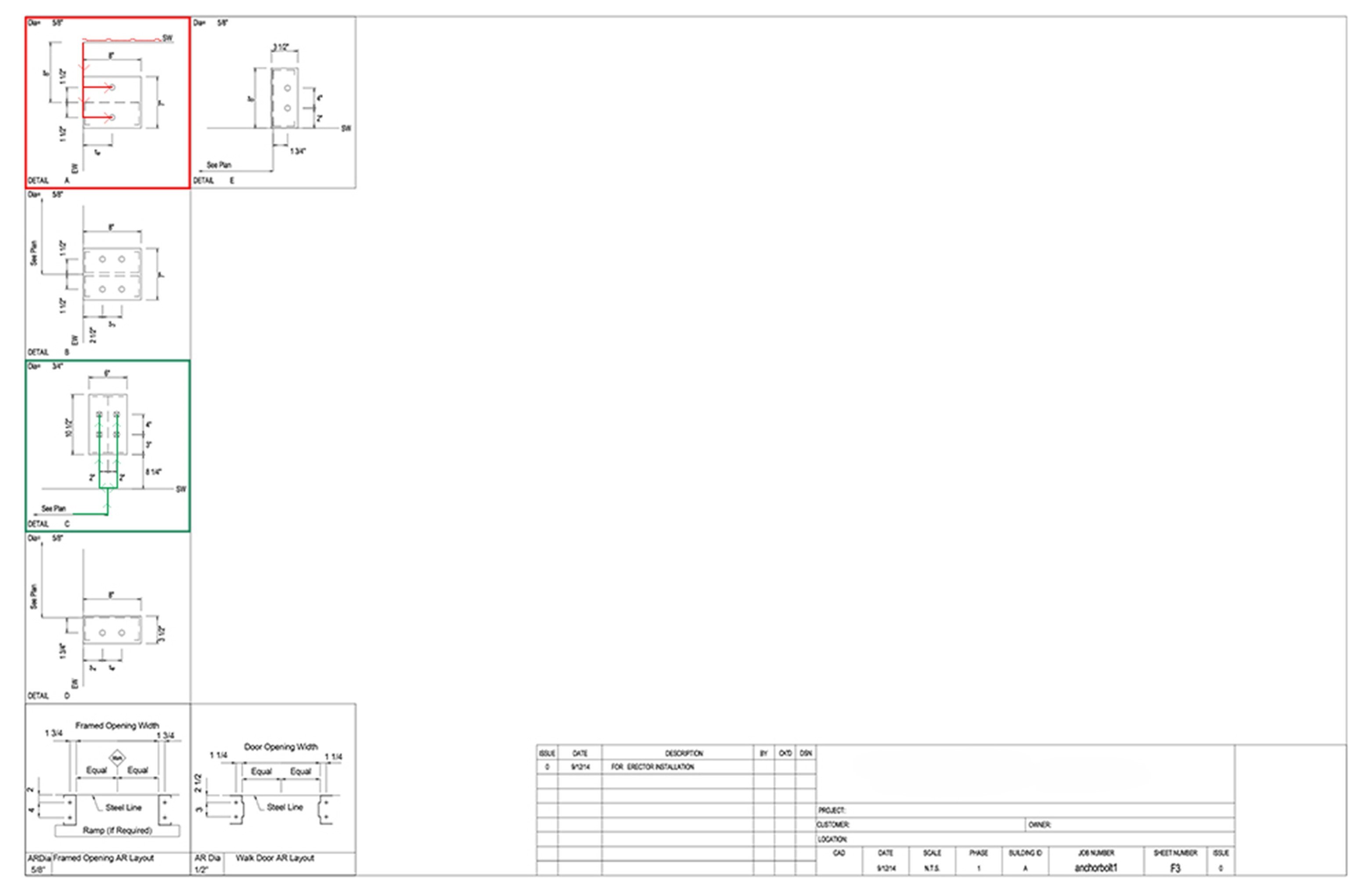
Details about each of the three color-coded sections are below. The color coding is here for demonstrative purposes, so that you can see where each highlighted section is located within the page.
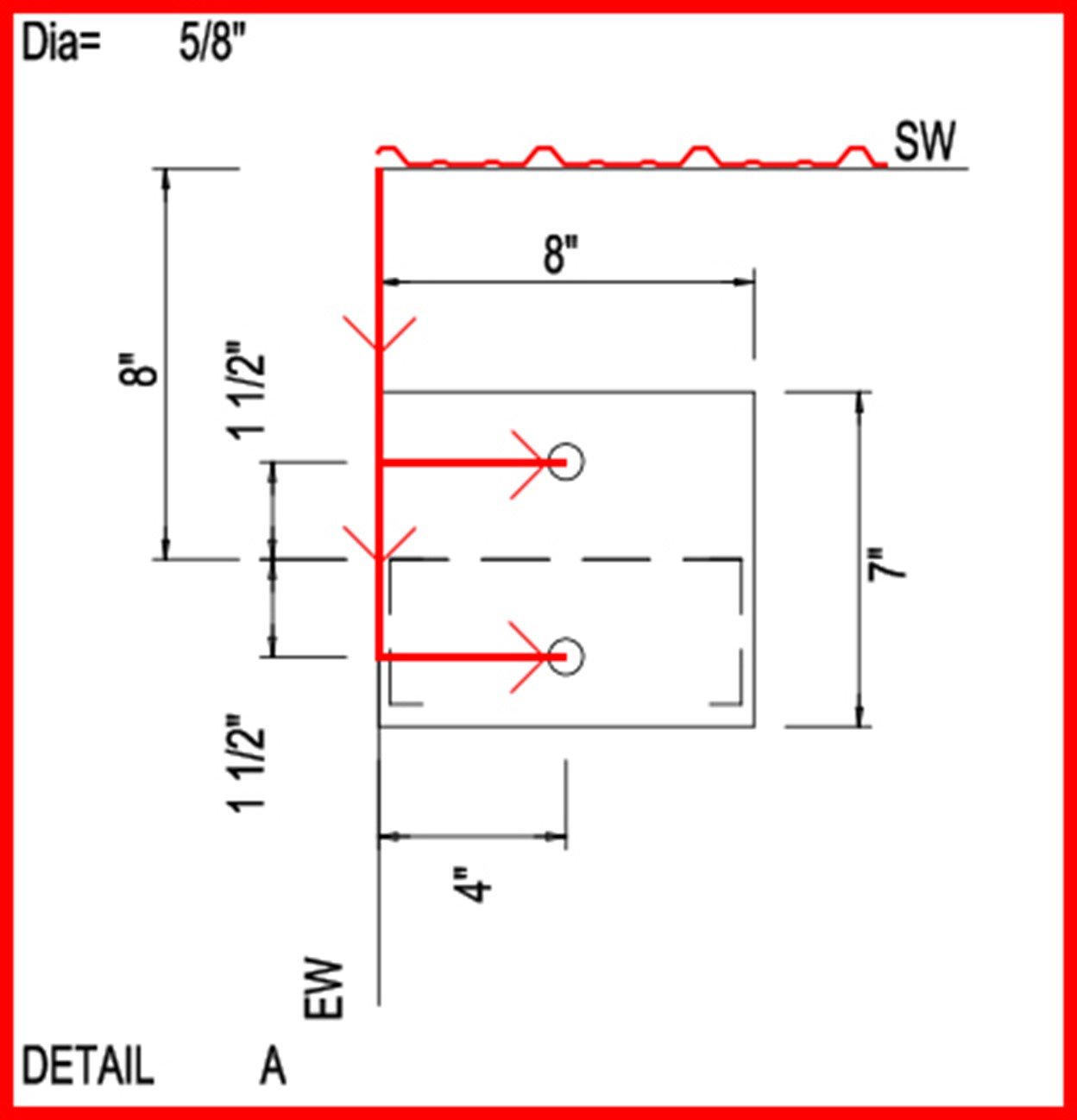
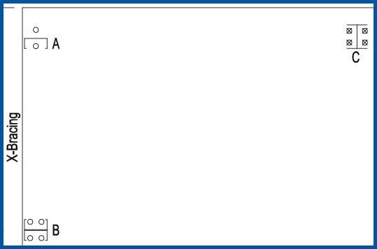
By looking in the lower-left corner of the image above, you can see it shows the details for Bolt Configuration A. In the upper-left corner, the diameter of the anchor bolt for this configuration – 5/8” – is shown. SW = sidewall, and EW = endwall. The wall lines shown are flush with the inside of the wall panels; depending on which panel profile you select, there will be a slight rib projection. A representation of PBR panel has been placed on the sidewall in the above image to demonstrate how it would project out.
Since this diagram shows both side- and endwalls, the configuration occurs at the corner of the building. The diagram also shows the steel plate that will attach to the anchor bolts is 8” x 7” and that there will be a C-channel column attached to the plate. The column should be anchored with the C-channel facing away from the sidewall, toward the center of the endwall, using two 5/8” anchor bolts.
To measure out the location of where the anchor bolts should be located for Bolt Configuration A, you would start by measuring 8-1.5=6.5” along the endwall from the corner. At that mark, you would then measure in 4” perpendicular to the endwall, which is where the center of the top bolt in the image will be located. Then you would measure 8+1.5=9.5” along the endwall from the corner, and then 4” in perpendicular to the endwall.
For the opposite corner of the building on that same endwall, you would simply reverse the direction from which you begin measuring. Remember to anchor the column with the C-channel facing in the proper direction – away from the nearest sidewall, toward the center of the endwall.
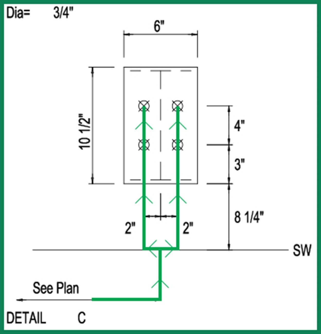
This image shows the details for Bolt Configuration C. The diameter of the anchor bolts for this configuration are 3/4″ and are shown with X’s through them, which is carried through on all three of the anchor bolt plan pages to denote which size bolts are placed in which locations.
This detail says to “See Plan”. The plan is covered in Part 2 of this series, and it shows the layout diagram of the different configurations for this sample building. Bolt Configuration C, as shown on the plan, occurs 6 times – once on each side of the 3 interior framelines of the sample building. As shown by the plan, these columns will be placed every 25 feet.
To measure where the columns will be located, mark every 25 feet on the sidewall. This gives you the location of the center of the plates. Then measure 2” back along the sidewall from the 25’ mark, and in 8.25+3=11.25” perpendicular to the sidewall. This is where the center of the bottom bolt in the image above will be located. Then go in another 4” on that same measure line to mark the center of the top bolt. Repeat this process measuring 2” on the other side of the center line of the plate. Repeat for all 6 plates.
These two examples should give enough instruction so that the other bolt configurations are easily deciphered.


Share